The Quiz Lamp Project (Fun with ESP8266 and MQTT)
Author: spellbinder, Date: 2019-01-17 14:00:00
Hello again fellow hackers,
in my free time I help out at two quiz events at my favorite pub, the "Rock- und Wikingerbar" (aka "Wikibar").
Every month we either have a Horror Movie Quiz or a Metal Quiz there and for that we faced a little problem.
For both the Metal and the Horror Quiz we have a section in each round where we utilize a LED projector for short clips and other stuff that people have to recognize or answer questions about the footage. In order to use a projector inside the pub we have to make the pub really dark. This includes taping molton cloth on all windows in order to block light from the street.
Of course this also means that we have to put lights on the tables so that people still can read their questionnaires.
Right now this is done using a bunch of tealights on each table but these have some serious downsides:
The problems with using tealights
- We can't extinguish the lights everytime the video section begins, because a) people wouldn't be able to read and b) it would take way too long to light them all up again.
- The tealights beam their light up, not down. This creates shadows and makes it harder to read.
- The bleeding light from them makes the image quality worse
A solution?
In order to solve this problem we found some cheap LED lamps with a rechargable 18650 battery inside and a touch button to turn them on with different brightness levels. We would need ten of these (two for each table). These lamps are reasonably cheap but have no remote control, so I immediately thought about using an ESP8266 microcontroller and create a local WiFi network which would allow us to control all the lamps immediately.
The journey begins...
I have to admit I've never worked with ESP8266 before this project started (but I do have experience with embedded software development) and thought this might be a great way to learn using these awesome little devices. To those of you who don't know what the ESP8266 is, first let me list some of its features:
- Low power µC (3.3 Volts, typical current draw is about 60 - 80 mA (peak 200 mA, also features deep sleep modes which draw almost no current at all)
- Integrated 802.11bg WiFi module
- 4 MBit flash memory
- 80 MHz CPU
- Lots of GPIO
- Versatile development choices available (NodeMCU Lua interpreter, Arduino libraries...)
- Low price (we'll get to that bit later on...)
So you can see that the ESP offers a lot of "bang per buck". Technology is awesome! We surely didn't have all these nice things when I started with electronics. All I had to play with were TTL logic gates or PLAs. Arduino didn't exist back in the day.
(Yeah yeah grandpa, stop talking about the war already...)
The idea
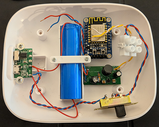
The idea I had in my head was to use the ESP8266 to control the LED inside these lamps using some sort of transistor and use PWM to control the brightness. A central management system then could be used to switch the light on/off or set the brightness. Obviously I had to do some research first about the electronics inside the lamps and what parts of it I could leave in and what I would have to remove. I also had to check that the current draw of the LED + ESP is not too high, because the quiz events last for several hours. So I was a bit worried that I'd have to do some power saving magic on the ESP programming part but in the end that wasn't necessary at all. After getting one of these lamps from Pearl for ~10 €, I was able to get a look inside of it:
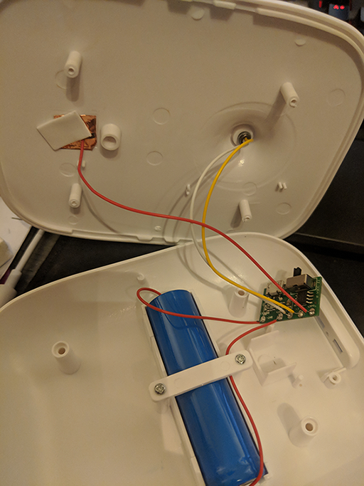
So the lamp has plenty of room for additional electronics. The charge controller and the touch controller are separate with the charging regulator being on the bottom of the board and the touch controller is that SO-8 package on the top layer. I had to desolder the touch controller IC because the switch on that PCB only switches that controller on/off. But since the end user shouldn't be allowed to change anything it's ok to desolder the chip. I'll definitely keep these ICs in my parts bin for future projects.
The quest for power
The good news is that I can just remove the touch control function without impacting the charging function.
The bad news is that the output is not 3.3 V regulated but directly connected to the positive terminal of the battery.
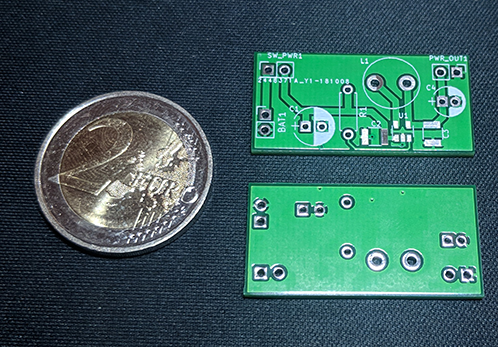
Which means that I had to create/buy some sort of power supply. Because I wanted to use every bit of energy the single 18650 cell has to offer, using a linear (even a low dropout) regulator was anathema to me. So I searched for complete 3.3 V DC-DC buck/boost converters that could work from 2.7 up to 5.5 Volts and provide at least 200 mA of current. Because I suck at searching for stuff I missed that some local electronics shop offers a LiPo module for the Weemos D1 mini. Instead I stumbled across the LM 3671 MF-3.3 DC/DC converter. So I ordered a bunch of those along with some of the required external components. What I didn't remember was how fucking tiny a SOT-23-5 package really is. When the package arrived and I saw how tiny these things are I was thinking: Ok, I definitely need to design a PCB for it as there is no way of using "dead bug soldering" to put it on a perfboard. At least no way with my shaky hands. (Then again it's a bad idea anyways to try and build a switching power supply on a piece of perfboard...)
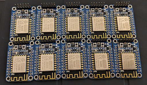
My good friend Sebastian Kulik helped me designing the PCB in KiCAD and I ordered the PCBs from JLCPCB... 10 PCBs for 2 € + ~5 € shipping. Sweet.
And after soldering all the components the power supply looks like this:
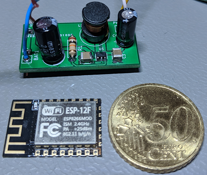
Don't ask me how long it took me to solder all these tiny fuckers... and since I've blown up one by connecting the battery in reverse I have to desolder that particular board completely and put fresh components on it. At least I was wise enough to buy plenty... and since I've completed 10 boards without one of them failing at all (apart from the one that was KIA'd by my stupidity) I have enough components in stock and enough experience in how to solder these tiny fuckers quickly.
The quest for the right ESP and a good datasheet/manual
Regarding the choice of the right ESP8266 module I was continuing my path of making bad decisions. I bought these almost "naked" modules which have no breakout board and a 2 mm pin pitch instead of 2.54 mm. Also I had to figure out how to put these modules into bootloader mode so I can program them with the Arduino IDE.
The included datasheet and lots of tutorials online just skipped over that critical part. You need to pull down GPIO0 and reset the chip so that it goes into bootloader mode. Once I figured that out I stumbled across another problem: Even with the simple blink sketch the boards had random WDT resets. After some research online I came to the conclusion that my jury-rigged breakout/flash board might be the culprit, because the power supply might be unstable. Which lead to the further conclusion that I need to get modules which are on a breakout board. I chose the Adafruit HUZZAH ESP8266 module which is rather pricey.
Later on a co-worker pointed me to cheaper modules (as in: half the price) but nevertheless there is one very good thing I have to say about the Adafruit module: The manual/datasheet is way better than anything I've found online so far regarding how to program the chip etc. it has no USB to serial converter on it, but that's fine because it has a LDO and a level shifter for the serial connection. Since I happen to have a USB to serial cable which already uses 3.3 V logic levels everything was fine. The level shifter isn't needed for that, but the LDO can be used to power the ESP from the serial cable, because it offers +5 V directly from the USB. So if you connect it to a powered USB hub or directly to one USB port on your computer (I wouldn't recommend doing that because you could short out your USB port and cause damage) you can power and flash the ESP very easy.
Stupid buying decisions, Part 1337
So I programmed my new Adafruit module with a simple test sketch and it was running perfectly fine. Then I placed it onto a breadboard and tried to power it up using one of my nice power supplies. Which showed the same or even worse behavior than with the "naked" ESP modules. It was then when I started measuring voltages on the power pins and to my surprise there was only 2.8 - 3 Volts. No wonder the naked ESPs failed, too.
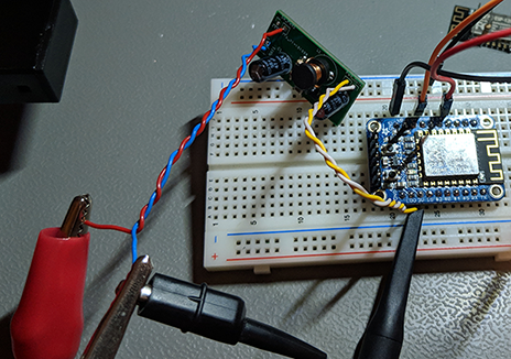
First I thought I ruined the PSU through bad soldering but then I started measuring right on the output of the PSU and the voltage was significantly higher. The same on the power input side. I fed the board with 5 Volts from my lab bench power supply but the reading dropped on the input side of the PSU aswell. Then I started measuring the wires I used to connect the PSU to the breadboard and the PSU to the lab power supply and found out that the cheap Chinese breadboard cables I used had a resistance of several ohms each. This explains the weird resets or the "not starting at all" behavior. If only I had measured things earlier. First rule of debugging circuits: Thou shall measure voltages! I didn't obey that rule and murphy bit me hard. This stupid mistake likely has cost me over 100 € worth of ESP modules. D'oh!
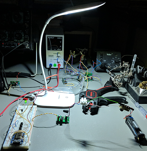
Lighting up the LED
After all these mistakes in buying bad stuff and using shitty wires I was finally able to control an LED over HTTP. At first I planned on using a N-Channel MOSFET for the job (IRF 510N) but was surprised that the LED was not very bright at all and that the MOSFET also seemed a bit unstable. Looking at the datasheet I found out that the 3.3 V logic level isn't enough to fully turn on the MOSFET. Fuck! Now what? I certainly can't output 5 V from a 3.3 V chip. Well, I grabbed a jellybean part I have always there: An ordinary BC 337-40 NPN BJT and calculated a base resistor that is high enough to drive the transistor "just" into saturation. Problem solved. Now the LED is bright enough and can be dimmed down for the video section of the quiz or turned off during breaks between rounds to save more battery.
End of the journey? Almost.
Recently I also had the idea to play a variation of "Jeopardy" on the Metal Quiz. This would require the use of some sort of "Quiz Buzzer" buttons. So I used 3 GPIOs as inputs and 3 as outputs. The lamp will later get three 2.5 mm stereo headphone jacks for connecting the buttons and a LED for each button. 3 quiz buzzers per lamp times 10 lamps equals 30 players possible. This should be enough for the average Metal quiz. And if this quiz format turns out to be successful we could easily add more lamps later. But in order to keep stuff synchronised, fast and still energy efficient I switched from using HTTP requests (the lamp polled the current brightness every 5 seconds and sent a HTTP request for each button press) to MQTT. This required the use of a Raspberry Pi as a MQTT broker but since I had to use some sort of WiFi Access Point anyway, this was no big deal. I used a Raspberry Pi 3 B+ for the job and installed hostapd, Mosquitto and Home Assistant on it. Now I can control the brightness of the lamps via Home Assistant and the Jeopardy game (which I'll write in Python with a HTML5 frontend) can receive MQTT messages about button presses via WebSockets and tell the winner (the one whose button press registered first) lamp to turn on the button's LED so everyone can see whose turn it is. For the horror quiz I even added a "flicker" trigger that will make the lamps flicker a bit when they receive a special MQTT message. Of course everything was setup using TLS encryption and per-lamp usernames+passwords. No amateur hour stuff when it comes to security! :D
This is the end (for now)
Yesterday I finished building everything into the prototype lamp and tested it extensively. The only things that are missing right now are the 2.5 mm jacks, stuff for the quiz buzzers (LEDs, resistors, button switches, a custom enclosure) and - obviously - 9 more lamps. Below is a link to a video of the prototype in action:
The Quiz Lamp Project
(Privacy warning: Link goes to YouTube!)